+86 18928646960+86 13630152584
Leave Your Message
Picking out the right Switch Potentiometer isn’t just about flipping through catalogs or eyeballing photos. It really all depends on what you’re actually using it for. Whether it's a dashboard dimmer, a lab instrument, or an audio amplifier, each has its own needs when it comes to electrical and mechanical behavior. And let’s not forget, every application comes with its own set of challenges—things like contact noise, shaft wear, sealing issues, or the risk of accidental switches popping on when you don’t want them.
Market reports like Research and Markets’ 2024 global Potentiometers outlook point out that sectors like automotive, industrial gear, and consumer electronics are the big drivers these days. The same reports link this growth to more automation and the trend towards smaller, more compact electronic systems. Meanwhile, MarketsandMarkets’ research on Human Machine Interfaces highlights the increasing demand for controls that are not only smaller but also easier to use. These trends mean one thing—component choices are getting tougher. Just because a part looks familiar doesn’t mean it’s the right fit.
Here’s where hands-on experience really matters.
Engineers need to dig into details—resistance value, tolerance, power rating, rotation angle, switch type, contact arrangement, and mounting dimensions. You’ll want to check the datasheet to see about electrical life, insulation resistance, and operating temperature ranges. If the device is going to be exposed to dust or moisture, pay close attention to sealing ratings. Just keep in mind — an IP rating is only meaningful if it matches the whole assembly, not just the part.
Companies like Bourns, ALPS Alpine, and Vishay publish extensive specs and qualification info, which is super helpful. But don’t take those ratings as a guarantee that the part will perform perfectly out in the field. Shaft feel can change after thousands of cycles, and soldering at the wrong temp can damage sensitive parts during assembly if your process isn’t under control. I’ve seen folks focus way too much on resistance values and forget to consider things like panel clearance or how far the switch actually travels—that’s a classic mistake.
A good, reliable choice comes down to a balance—look at technical specs, gather user feedback, check availability, and ensure it’s been tested for longevity. Always compare at least two solid options. And, of course, don’t forget to test the actual assembled product. This guide is here to help you make smarter, practical decisions with measurable criteria, and a bit of healthy skepticism about the usual assumptions.
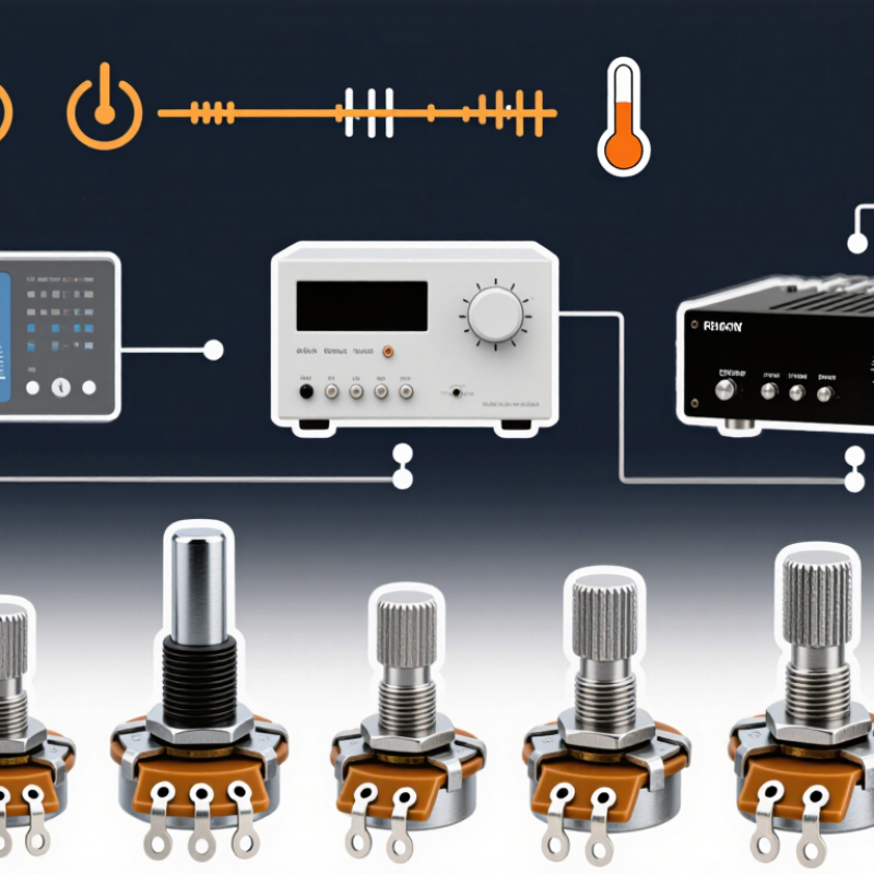
How to Choose the Right Switch Potentiometer?
Understanding the Structure and Function of a Switch Potentiometer
A switch potentiometer combines two controls in one compact component. The potentiometer adjusts electrical resistance, while the switch opens or closes a separate circuit. Inside, a resistive track connects to two outer terminals. A movable wiper slides across this track through the rotating shaft. The wiper terminal provides a changing output voltage or resistance. The switch mechanism usually operates at the shaft’s end position. Listen for a clear click.
When selecting one, check the resistance value, taper, power rating, and switch specifications. A linear taper changes evenly and suits measurement or control circuits. An audio taper often feels more natural for sound levels. The switch needs its own voltage and current ratings. Do not assume the potentiometer rating covers the switch contacts. They are separate electrical paths. Shaft length and bushing size also matter during installation. A loose fit can make adjustment feel unreliable.
Practical testing reveals details that datasheets sometimes hide. Turn the shaft slowly and watch for jumps in resistance with a multimeter. Check whether the switch activates consistently at the same position. In bench work, I have found that excessive mechanical force can damage the internal wiper. That mistake is easy to repeat. Detents may improve control, but they can also feel too stiff for frequent adjustment. Temperature, dust, and repeated cycling deserve attention before final selection. A small tolerance in resistance may be acceptable, but unstable switching is not.
| Selection Dimension | What It Means | Typical Options or Values | Recommended Choice by Application |
|---|---|---|---|
| Resistance Value | The total resistance between the two outer terminals. It determines the available adjustment range and affects circuit current. | Common values include 1 kΩ, 5 kΩ, 10 kΩ, 50 kΩ, 100 kΩ, 250 kΩ, 500 kΩ, and 1 MΩ. | Use the value specified by the circuit design. For many analog control inputs, 10 kΩ is a common compromise between loading and noise. |
| Resistance Taper | The relationship between shaft rotation and resistance change. | Linear: proportional change. Logarithmic or audio: gradual change at one end and faster change at the other. Reverse-logarithmic: opposite audio response. | Choose linear for voltage setting, position sensing, and many control circuits. Choose logarithmic for audio volume because it better matches human hearing. |
| Switch Function | The integrated switch opens or closes a separate electrical circuit when the shaft is pressed, pulled, or rotated to a defined position. | Push-on/push-off, momentary push switch, end-stop switch, or rotary switch. Contact arrangements may include SPST, SPDT, or DPDT. | Use push-on/push-off for power or mode selection. Use momentary action for reset, menu input, or temporary control signals. |
| Contact Arrangement | Defines how many independent circuits the switch can control and whether each circuit is normally open or changeover. | SPST: one circuit, on/off. SPDT: one common terminal switches between two outputs. DPDT: two simultaneous changeover circuits. | Select SPST for simple on/off control; SPDT for signal routing; DPDT when two circuits must change state together. |
| Power Rating | The maximum power the resistive element can dissipate without excessive heating or premature failure. | Small panel potentiometers are often rated from approximately 0.05 W to 0.5 W; larger units may support higher power. | Calculate circuit dissipation using P = V²/R or P = I²R. Keep the expected power below the specified rating, with safety margin. |
| Switch Contact Rating | The maximum voltage and current that the integrated switch contacts can safely interrupt or carry. | Ratings vary widely. Low-level signal contacts may be intended for logic or analog signals, while power-rated versions can handle higher voltage and current. | Check both AC and DC ratings. Do not assume a potentiometer’s resistance power rating also applies to its switch contacts. |
| Element Technology | The resistive material affects cost, noise, durability, adjustment feel, and allowable power. | Carbon: economical and widely used. Conductive plastic: smooth operation and low noise. Cermet: good stability and adjustment accuracy. Wirewound: high power and resolution but may have discrete steps. | Choose conductive plastic for smooth low-noise adjustment, cermet for precision trimming, and wirewound for higher power requirements. |
| Rotation Angle | The mechanical angle through which the shaft can be rotated from one end stop to the other. | Common panel potentiometers use approximately 270° of rotation. Multi-turn versions provide several complete rotations for finer adjustment. | Use single-turn types for quick user controls. Use multi-turn types when precise adjustment and greater setting resolution are required. |
| Resolution and Wiper Noise | Resolution describes the smallest practical adjustment; wiper noise is the electrical variation produced during movement or vibration. | Wirewound elements can exhibit step-like changes. Conductive-plastic elements generally provide smooth adjustment and low contact noise. | For audio, instrumentation, and precision feedback, prioritize a smooth element, low wiper noise, and adequate adjustment resolution. |
| Shaft and Mounting Style | The shaft and mounting arrangement determine mechanical compatibility with the panel, knob, and circuit board. | Round or flat shaft; knurled shaft; slotted shaft; panel mount; board mount; horizontal or vertical PCB orientation. | Match shaft diameter, shaft length, bushing or threaded mounting dimensions, terminal spacing, and PCB layout before ordering. |
| Operating Temperature | The temperature range in which the potentiometer and switch are expected to operate within specification. | Many commercial components are specified around −10°C to +70°C; industrial versions may support wider ranges such as −40°C to +85°C. | Select a rated temperature range wider than the equipment’s actual internal and ambient conditions. |
| Environmental Protection | Protection against dust, moisture, vibration, and contamination that can affect the resistive track or switch contacts. | Open construction, dust-resistant construction, sealed shaft, or sealed body. Formal ingress ratings depend on the specific component. | Use sealed or protected construction for industrial panels, outdoor equipment, dusty environments, or applications exposed to cleaning fluids. |
| Electrical Travel | The portion of mechanical shaft travel over which the resistance changes as specified. | Usually covers most of the rotation but may not exactly equal the full mechanical travel because of end zones and tolerance. | Confirm the electrical angle and end-terminal resistance when the control must reach a predictable minimum or maximum value. |
| Tolerance | The permitted difference between the marked resistance and the actual end-to-end resistance. | Common resistance tolerances include ±10% and ±20%; precision parts can have tighter tolerances. | Use tighter tolerance when the potentiometer is part of a calibrated divider or gain-setting circuit; otherwise, standard tolerance may be sufficient. |
| Expected Service Life | The number of adjustment cycles or switching operations the component is designed to withstand under specified conditions. | Service life varies by construction, load, environment, and operating force. Potentiometer and switch cycle ratings may be specified separately. | Choose a higher cycle rating for frequently adjusted controls, service equipment, laboratory instruments, and user interfaces. |
| Electrical Interface | The terminal arrangement and signal configuration used to connect the resistive element and integrated switch. | Three terminals for a standard potentiometer; additional terminals for the switch. Some versions include dual-gang elements for two synchronized channels. | Verify terminal numbering, gang tracking, independent or linked shafts, and the required schematic connection before PCB production. |
| Safety and Verification Checklist | A final check that the electrical, mechanical, environmental, and functional requirements are all compatible. | Confirm resistance, taper, power, switch rating, contact arrangement, dimensions, temperature range, sealing, cycle life, and terminal layout. | Choose the part only after comparing its datasheet values with the worst-case circuit load and actual installation environment. |
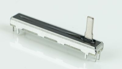
The SC4521N 60MM slide potentiometer is designed for smooth, accurate control in audio mixer fader applications. Its 60 mm sliding travel provides a comfortable adjustment range for volume, channel balance, and other signal parameters. The linear slider format supports quick visual positioning, allowing operators to make precise changes during recording, live sound management, broadcasting, and audio equipment testing. Its specification can be customized to match different panel layouts, resistance requirements, and control preferences.
Beyond mixer consoles, this sliding potentiometer can be used in audio amplifiers, speakers, home appliances, medical equipment, communication devices, and remote-control systems. Depending on the equipment design, it may regulate light intensity, motor speed, pressure, temperature, or audio output. For reliable integration, designers should consider mounting dimensions, slider height, electrical characteristics, operating force, and expected service life before production. With a minimum order quantity of 2,000 units and manufacturing support from Guangdong, China, it is suitable for customized equipment projects and medium- to large-scale production.
It combines adjustable resistance with a separate switching function. The shaft moves a wiper across a resistive track. The switch opens or closes another circuit. These are separate electrical paths.
Check the circuit schematic before copying an old label. Measure the resistance across the two outer terminals. Record the reading at room temperature. Small differences matter. Tolerance can affect sensitive controls.
A linear taper changes resistance evenly as the shaft turns. It suits brightness, speed, and calibration controls. An audio taper changes more naturally for volume adjustment. Turn the shaft slowly. Listen for sudden jumps.
Connect a multimeter across the outer terminals. Measure the wiper at several positions. Try 25, 50, and 75 percent rotation. The readings should follow the intended taper. Unstable readings need attention.
SPST provides a basic on-off function. SPDT connects one input to either of two outputs. DPDT controls two circuits together. Label every terminal before wiring. Similar layouts can mislead.
Check the switch voltage and current ratings separately. Do not rely on the potentiometer rating. The switch must handle the real load. Leave a safety margin. Average operating current is not enough.
A latching switch stays active after release. A momentary switch returns after the control is released. Match this action with the equipment’s control logic. Test the behavior repeatedly. One test may not reveal wear.
Check shaft length, bushing size, panel thickness, and rotation angle. Confirm knob clearance before installation. A loose fit can feel unreliable. Measure with a ruler. Assumptions sometimes fail.
Dust, heat, repeated cycling, and mechanical force can affect performance. Excessive force may damage the internal wiper. Detents can improve control but feel stiff. Check continuity in every switch position. I still recheck wiring.
Choosing the right Switch Potentiometer requires more than selecting a resistance value. First, understand how its rotary control and integrated switch operate, then determine the required resistance and taper for smooth, predictable adjustment. Consider whether the switch should be activated by pressing, pulling, or rotating the shaft, and verify that its contact arrangement matches the circuit’s control needs. Power, voltage, and current ratings must also be suitable for the application, with enough margin to support reliable operation and prevent premature wear.
Physical compatibility is equally important. Check the shaft shape, length, mounting method, panel space, and overall dimensions before installation. The potentiometer should also match the circuit’s wiring and connector requirements. Finally, evaluate durability, environmental conditions, rotation angle, switching action, and operating feel. A well-selected component should provide comfortable control, stable electrical performance, and dependable service throughout its expected operating life.