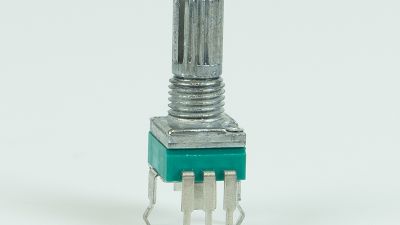
Industrial machines don’t usually break down in dramatic, obvious ways. Often, it’s just a tiny misalignment or small error in position that can quietly mess up a whole batch — and that’s where a Rotary Encoder really comes into play. This little device takes shaft movement and turns it into electrical signals that the controllers can read. Engineers rely on that feedback to fine-tune speed, angles, and travel distances. You see it in packaging lines, robotic joints, and conveyor systems — having accurate signals means the equipment can react quickly, preventing small issues from turning into bigger problems later on. But, when choosing one, it’s not just about resolution; you’ve also got to think about the environment, how well it fits into your system, how easy it is to maintain, and what happens if there’s downtime.
Honestly, the first step in picking a good encoder is really understanding your machine. Is the shaft exposed to dust, vibrations, water from washdowns, or temperature swings? Do you need incremental pulses or an absolute position readout if power gets cut? Magnetic, optical, and other types of encoders each have their own pros and cons, so those choices matter too. Plus, make sure the electrical specs match up — things like voltage, output type, signal frequency, and shielding. Even a super-high-tech encoder can be a letdown if its connector isn’t secure or if its resolution is overkill for what your control system actually needs. So, fitting the right encoder is key.
Of course, selecting an encoder isn't just about shiny datasheets and specs. You should dig into installation guides, test results, and service histories. Double-check mounting tolerances and alignment—this stuff can make or break the system’s accuracy before you even start production. It’s also smart to ask how the device performs under dirty conditions, shocks, or unexpected stops — no device is foolproof, and even seasoned teams sometimes overlook things like cable routing or grounding. Don’t ignore those details, they really matter. When you pick the right Rotary Encoder, it can boost repeatability, keep your product quality high, or even help catch issues early with predictive maintenance. But honestly, all these benefits only come if the sensor, the controller, the mechanics, and the operators are all working together smoothly — it's a true team effort.

A rotary encoder is a sensor that measures rotational movement. It converts shaft position, speed, and direction into electrical signals. Inside, a rotating disk or magnetic target moves with the shaft. A stationary sensing element detects each change. The controller then interprets these signals as motion data.
There are two common types: incremental and absolute. An incremental encoder produces pulses as the shaft turns. Two output channels, often called A and B, reveal direction through their phase difference. A separate index signal can mark one reference position. An absolute encoder provides a unique position value, even after power returns. This distinction matters in conveyors, robotic joints, machine tools, and motor feedback systems.
Installation details affect real performance. A technician should inspect the Rotary Encoder Pin connection, cable shielding, and supply voltage before testing. Loose wiring can resemble a software fault. It is not magic. Mechanical coupling must also stay aligned, because vibration can create false counts or shorten bearing life. In dusty areas, sealing and cleaning routines deserve attention. I have seen troubleshooting begin with complicated diagnostics, while a damaged connector caused the error. That assumption can fail. Signal resolution also needs practical review; more pulses do not automatically produce better control if the system cannot process them reliably. Calibration records, measured shaft speed, and repeatable test conditions help engineers verify accuracy over time.
A rotary encoder gives industrial machines a clear position signal during demanding motion control tasks. It converts shaft movement into feedback that a controller can interpret quickly. This supports accurate speed regulation, positioning, and coordinated movement. In a packaging line, even a small angular error can misalign labels or damage materials.
Industrial models need more than high resolution. They should resist vibration, dust, oil mist, and repeated temperature changes. Sealed housings protect internal sensing elements near motors and gearboxes. Strong bearings also reduce shaft movement during sudden starts and stops. An incremental encoder suits many speed-control systems, while an absolute encoder retains position data after power loss. The correct choice depends on control architecture, not resolution alone.
Electrical performance matters just as much. A stable output signal helps reduce missed counts caused by electromagnetic interference. Shielded cables, proper grounding, and compatible voltage levels should be checked during installation. A Pcb Rotary Encoder can support compact control panels, but its circuit-board connections require careful inspection. Loose terminals create faults that may appear random. They are not always random.
From field maintenance experience, alignment is often overlooked. A slight coupling offset can produce premature bearing wear and unstable feedback. I still recommend checking shaft runout, mounting tolerance, and operating temperature before approval. Datasheets provide limits, but real machines add dust, vibration, and imperfect installation. Testing under actual load may reveal weaknesses that bench testing misses.
In industrial machinery, position feedback must remain dependable through heat, vibration, and repeated movement. A rotary encoder translates shaft rotation into electrical signals that a controller can interpret. This feedback shows whether a valve, conveyor, or robotic joint has reached its intended angle. The benefit is practical: repeatable feedback supports tighter motion control and reduces guesswork during operation. High-resolution encoders detect small angular changes, while absolute encoders retain position information after power loss. That difference matters when restarting equipment safely and accurately.
During commissioning, I have seen a small alignment error create unstable readings. A flexible coupling may appear acceptable, yet vibration can introduce unwanted position changes. Technicians should inspect shaft alignment, mounting rigidity, grounding, and cable shielding. Dust, oil, moisture, and washdown conditions also influence long-term reliability. Choose a suitable protection rating and match the encoder output to the control system. More pulses do not automatically mean better accuracy. Signal quality, bearing condition, and controller resolution must work together. I have sometimes treated encoder data as absolute truth. That was a mistake. Comparing readings with a known reference angle can reveal drift before it disrupts production.
| Selection Dimension | Incremental Optical Encoder | Absolute Optical Encoder | Magnetic Encoder | Industrial Benefit |
|---|---|---|---|---|
| Position output | Relative position through A/B quadrature pulses; an index pulse may mark one reference point per revolution. | Digital position value available directly from the encoder, commonly using serial or fieldbus communication. | Position derived from changes in a magnetic field and reported as incremental or absolute data. | Enables closed-loop motion control, speed regulation, synchronization, and machine sequencing. |
| Typical resolution | From tens to several thousand pulses per revolution; quadrature decoding can provide up to four counts per pulse cycle. | Commonly 12 to 20 bits per revolution in industrial designs, equivalent to 4,096 to 1,048,576 position counts. | Often from a few hundred counts to several thousand counts per revolution, depending on sensing technology and electronics. | Supports accurate positioning without relying solely on mechanical stops or timed movements. |
| Position accuracy | Primarily affected by signal interpolation, bearing runout, shaft coupling, alignment, and mechanical system error. | Typically specified in angular degrees or arcminutes; system-level accuracy also depends on mounting and mechanical transmission. | Generally lower than high-precision optical designs, but suitable for many speed and position feedback applications. | Provides repeatable feedback for reducing positioning error and improving process consistency. |
| Power-up behavior | Usually requires a homing or reference routine after power loss unless backed up by an external position system. | Can report absolute shaft position immediately after power-up, subject to the encoder’s operating and communication conditions. | Absolute versions can retain position information; incremental versions generally require referencing. | Reduces startup time and helps avoid unnecessary homing cycles in automated equipment. |
| Maximum rotational speed | Often well suited to high-speed motor feedback; the practical limit is set by bearing, disk, signal frequency, and electronics. | High-speed operation is possible, but communication update rate and data-processing requirements must be considered. | Suitable for many medium- and high-speed applications; magnetic sensing is generally tolerant of dust and vibration. | Allows precise speed control and stable operation across changing loads and motion profiles. |
| Resistance to contamination | Optical components may be affected by dust, oil, condensation, or particles if sealing and contamination control are inadequate. | Requires appropriate sealing and installation practices in environments with dust, oil, moisture, or process debris. | Usually offers strong tolerance to dust, dirt, and vibration because sensing does not depend on an exposed optical path. | Improves reliability in manufacturing, packaging, material handling, and mobile machinery. |
| Electrical interface | Common outputs include push-pull, line-driver, and open-collector pulse signals. | Common interfaces include synchronous serial links, industrial Ethernet, and other digital communication protocols. | Available with pulse, analog, or digital outputs depending on the sensing architecture. | Makes it possible to match feedback hardware with PLCs, servo drives, motion controllers, and safety systems. |
| Typical applications | Motor speed feedback, conveyors, pumps, indexing systems, and basic servo positioning. | Robotics, servo axes, machine tools, automated assembly, telescopic mechanisms, and precision positioning. | Packaging equipment, actuators, mobile machinery, food-processing equipment, and applications exposed to contamination. | Provides a scalable feedback option for both high-precision systems and demanding industrial environments. |
| Main design consideration | A reliable reference strategy and correct pulse-frequency calculation are essential. | Network compatibility, data latency, configuration, and power-loss behavior should be verified. | Magnetic-field interference, air gap, installation alignment, and required accuracy must be evaluated. | Proper specification ensures dependable feedback, predictable maintenance, and longer service life. |
Why Choose a Rotary Encoder for Industrial Applications?
Comparing Rotary Encoders with Other Position Sensors
In industrial machines, position feedback affects speed, timing, and product consistency. A rotary encoder converts shaft movement into digital pulses or an absolute angle. Compared with potentiometers, it avoids sliding electrical contact and usually supports more operating cycles. That matters on indexing tables, valve actuators, and conveyor rollers. An Ec11 Rotary Encoder can suit compact control panels and small mechanisms. Its real suitability still depends on resolution, sealing, wiring, and signal requirements.
Optical encoders can deliver fine resolution, but dust and oil may weaken their light path. Magnetic encoders tolerate dirt better, although nearby metal and electrical noise can affect readings. Resolvers offer strong performance in harsh environments, yet they often require more complex electronics. Potentiometers remain affordable for low-duty feedback. Their resistive tracks can wear and produce unstable readings. No sensor wins every test.
During hands-on commissioning, engineers should check misalignment, vibration, temperature, and cable routing. A stable reading at room temperature proves little. Connector strain is often overlooked during machine trials. One imperfect installation can create pulses that resemble mechanical failure. The output format must match the controller, not merely the highest resolution. In wet areas, sealed construction deserves as much attention as nominal accuracy.
Selecting a rotary encoder starts with the motion, not the catalogue. Define shaft speed, travel, acceleration, mounting space, and required accuracy. Incremental encoders suit speed and position feedback with simple control systems. Absolute encoders retain position data after power loss. That difference matters on robotic joints and indexing tables.
The International Federation of Robotics reported 541,302 industrial robots were installed worldwide in 2023. More automated axes mean feedback devices face tighter uptime demands.
Resolution must match the controller and mechanical tolerance. Higher resolution is not automatically better. It can increase data volume, wiring demands, and troubleshooting time. Check the output interface, signal frequency, shaft load, vibration rating, and operating temperature.
For dusty washdown areas, verify the complete enclosure rating, not only the sensor housing. IEC 60529 defines IP protection levels, but real installations often expose weak cable glands. That detail is easy to miss.
Safety-related machinery needs a separate review. Assess diagnostic coverage, failure behavior, and applicable requirements under ISO 13849-1 or IEC 61800-5-2.
A practical test should run the encoder through startup, overspeed, vibration, and power interruption conditions. Document the results.
Engineers sometimes select by resolution alone, then discover that connector access is poor. I have seen that mistake delay commissioning. It is avoidable, but only when the application is measured before the encoder is ordered.
A rotary encoder can deliver precise position feedback, but reliable operation begins at installation. The shaft must align with the driven mechanism. Even small misalignment can create bearing load, signal fluctuation, and premature failure. Use a flexible coupling within its specified limits, then check runout with a dial indicator. Keep the Rotary Encoder Knob accessible, but protect it from accidental impact.
Cable routing also matters. Separate encoder wiring from motor power cables. Use shielded twisted pairs where the control system requires them. Connect the shield according to the equipment’s grounding design, not by habit. Seal unused cable entries. Dust is often underestimated. The U.S. Department of Energy’s Operations & Maintenance Best Practices Guide reports that preventive maintenance can reduce maintenance costs by 12–18% compared with reactive work. That figure supports scheduled inspection, but it does not replace engineering judgment.
During maintenance, inspect coupling wear, mounting screws, connector seals, and abnormal vibration. Record pulse errors beside temperature and operating hours. A simple trend can expose a loose mount before production stops. IEC 60068 environmental testing principles also remind engineers to consider vibration, humidity, and thermal cycling during equipment selection. The specified IP rating must match the real enclosure environment. Not the brochure’s ideal conditions. A technically correct encoder can still fail when condensation enters after a washdown cycle. Maintenance intervals should therefore reflect actual duty, contamination, and shock exposure. Our assumptions deserve review.
The RK097N A503 rotary potentiometer with switch is designed for convenient control of volume, lighting, speed, pressure, and temperature. Its rotary structure allows users to make smooth, precise adjustments, while the integrated switch supports simple on/off operation in compact control panels. With customizable specifications, it can be adapted to different equipment designs, installation requirements, and operating environments.
This component is suitable for audio amplifiers, speakers, household appliances, medical equipment, communication electronics, remote-control equipment, and other electronic products requiring manual adjustment. When selecting a suitable version, buyers should consider resistance value, shaft style, rotation angle, switch configuration, mounting method, and panel space. These details help ensure compatibility with the intended circuit and enclosure.
For projects requiring customized production, technical drawings and electrical requirements should be confirmed before ordering. The product is manufactured in Guangdong, China, and the minimum order quantity is 2,000 units. Buyers should also verify sample availability, customization options, packaging, lead time, and inspection procedures. Clear communication about the application and expected operating conditions can help achieve consistent performance across different equipment models.
It converts shaft rotation into electrical signals. A controller reads those signals to track position and movement.
It confirms whether a valve, conveyor, or robotic joint reached its target angle. This reduces guesswork during operation.
Incremental encoders report movement through pulses. Absolute encoders retain position information after power loss. That helps during safer restarts.
Not always. Signal quality, bearing condition, alignment, and controller resolution must work together.
Align the shaft carefully with the driven mechanism. Use a flexible coupling within its limits. Check runout with a dial indicator.
Loose mounting, shaft misalignment, and excessive vibration can distort feedback. A coupling may look acceptable but still transmit movement errors.
Keep encoder wiring separate from motor power cables. Use shielded twisted pairs when required. Follow the equipment’s grounding design.
Dust, oil, condensation, and washdown water can damage signals or internal parts. Select a protection rating for real conditions, not ideal brochure conditions.
Inspect coupling wear, mounting screws, connector seals, and unusual vibration. Record pulse errors with temperature and operating hours.
Compare encoder readings with a known reference angle. A simple trend can reveal drift early. I once trusted feedback too much. That was a mistake.
A Rotary Encoder is a sensing device that converts shaft rotation into electrical signals, allowing control systems to determine position, speed, direction, and movement over time. In industrial applications, its high resolution, fast response, repeatability, and ability to provide continuous feedback make it valuable for accurate motion control. Compared with simpler position sensors, rotary encoders can support more detailed feedback and reliable performance in automated machinery, robotics, conveyors, and production equipment.
Selecting the right rotary encoder requires evaluating resolution, output type, operating speed, environmental protection, shaft design, mounting space, and compatibility with the control system. Installation should ensure correct alignment, secure connections, and protection from vibration, dust, moisture, and excessive mechanical loads. Regular inspection of cables, couplings, mounting hardware, and signal quality can help prevent errors and extend service life. With proper selection, installation, and maintenance, a Rotary Encoder can improve operational accuracy, efficiency, and reliability in demanding industrial environments.